Our Vision & Your Project
Welcome to the Teddy's Cleaning Tech Hub! Founded by Ethiopian-Australian entrepreneur Tewedros "Teddy" Gebruwubet, we're passionate about the future of cleaning. While we dream of and actively research robotics solutions (note: we don't currently deploy cleaning robots in our services), we also believe in sharing knowledge and empowering our community.
This page is dedicated to that spirit of innovation and education. Here, we provide a completely free, step-by-step guide to building your own practical device: a DIY Environment Monitor using Arduino. It's a fantastic way to learn about sensors, microcontrollers, and how technology can help us understand and improve our surroundings.
Whether you're a bar owner, manager, student, or just a curious DIY enthusiast, this project is for you. Let's explore the potential of technology together!
DIY Environment Monitor Guide
Project Overview: Breathe Easy!
Ever wondered about the air quality in your bustling bar or venue? Or wanted a quick check on whether the temperature and humidity are just right for your patrons and staff? Today, we're diving into a fun and practical DIY project: building an Arduino-based Bar Environment Monitor!
This nifty device will keep an eye on:
- Air Quality: Using an MQ-135 sensor to detect VOCs, smoke, alcohol fumes, and other airborne "stuff" that can make a place feel stale or indicate a need for cleaning/ventilation.
- Temperature & Humidity: Using a DHT11 sensor to ensure the comfort of everyone in your establishment.
- Real-time Display: All this info will be shown on a compact OLED screen with easy-to-understand status updates and even action prompts for your staff!
This project is perfect for bar owners, managers, or any DIY enthusiast looking to create a smart, useful gadget. It's a great way to get proactive about your venue's atmosphere. Let's get building!

Step 1: Gather Your Components
Here are the bits and pieces for our Environment Monitor. We've included example links, mainly to Australian suppliers or common international sites. Prices and availability can vary, so shop around!
| Component | Purpose | Example Sourcing (Australia) | Notes |
|---|---|---|---|
| Arduino Nano V3.0 (with CH340 chip) | The brains of the operation | Core Electronics / Jaycar | Ensure it's a Nano V3.0 |
| USB Cable (Mini-B type) | To program and power the Nano | Usually included with Nano | Check if included |
| MQ-135 Air Quality Sensor Module | Detects various gases | Core Electronics / Jaycar | Module version is easier |
| DHT11 Temperature & Humidity Sensor Module | Measures temp & humidity | Core Electronics / Jaycar | Blue module is common |
| 0.96" I2C OLED Display Module (128x64 SSD1306) | Displays the data | Core Electronics / Jaycar | Ensure it's I2C (4 pins) |
| Solderless Breadboard (Half or Full-size) | For easy connections | Core Electronics / Jaycar | Half-size is usually sufficient |
| Jumper Wires (Male-to-Male) | Connecting components | Core Electronics / Jaycar | A pack of 40-60 is good |
Disclaimer: Links are for illustrative purposes only. Teddy's Cleaning Services is not affiliated with these suppliers. Always check component specifications before purchasing.
Step 2: Software & Libraries Setup
Install Arduino IDE:
If you don't have it, download and install the latest version from the official Arduino website.
Install Required Libraries:
We need a few libraries to make our sensors and display work easily. Install them through the Arduino IDE's Library Manager:
- Open the Arduino IDE.
- Go to Sketch > Include Library > Manage Libraries...
- Search for and install the following libraries one by one:
- Adafruit SSD1306 (by Adafruit). When prompted, click "Install all" or "Install" to also get the required Adafruit GFX Library.
- DHT sensor library (by Adafruit). When prompted, click "Install all" or "Install" to also get the required Adafruit Unified Sensor library.
Once these are installed, your IDE is ready to talk to the hardware!
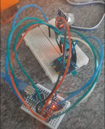
Step 3: Wiring It Up!
Time to get hands-on. Grab your breadboard and jumper wires. Here�s how to connect everything to your Arduino Nano. We recommend placing the Nano on the breadboard first, spanning the central divider.
Connection Table:
| Component | Module Pin | Arduino Nano Pin | Notes |
|---|---|---|---|
| OLED Display | VCC | 5V | Power |
| OLED Display | GND | GND | Ground |
| OLED Display | SCL | A5 | I2C Clock |
| OLED Display | SDA | A4 | I2C Data |
| DHT11 Sensor | VCC / + | 5V | Power (Check pinout) |
| DHT11 Sensor | GND / - | GND | Ground |
| DHT11 Sensor | DATA / S | D2 | Digital Pin 2 |
| MQ-135 Sensor | VCC | 5V | Power |
| MQ-135 Sensor | GND | GND | Ground |
| MQ-135 Sensor | AOUT | A0 | Analog Pin 0 |
| MQ-135 Sensor | DOUT | Not Used | Digital Out (Optional) |
Quick Wiring Steps:
- Place your Arduino Nano on the breadboard.
- Connect the Nano's 5V and GND pins to the power rails (usually red for +/5V, blue for -/GND) on your breadboard using jumper wires. This makes distributing power easier.
- OLED: Connect its 4 pins: VCC to the 5V rail, GND to the GND rail, SCL to Nano pin A5, SDA to Nano pin A4.
- DHT11: Connect its 3 pins: VCC/+ to the 5V rail, GND/- to the GND rail, DATA/S to Nano pin D2. (Pin order can vary, check your module!)
- MQ-135: Connect its VCC to the 5V rail, GND to the GND rail, and AOUT to Nano pin A0.
Double-check all your connections carefully before proceeding! Incorrect wiring can damage components.

Step 4: The Code
Here's the full Arduino sketch for the Environment Monitor. Copy this code and paste it into a new sketch in your Arduino IDE (File > New).
#include <Wire.h>
#include <Adafruit_GFX.h>
#include <Adafruit_SSD1306.h>
#include <DHT.h>

// OLED Display settings
#define SCREEN_WIDTH 128
#define SCREEN_HEIGHT 64
#define OLED_RESET    -1 // Reset pin # (or -1 if sharing Arduino reset pin)
#define SCREEN_ADDRESS 0x3C // Common address, use I2C scanner if display doesn't work
Adafruit_SSD1306 display(SCREEN_WIDTH, SCREEN_HEIGHT, &Wire, OLED_RESET);

// DHT Sensor settings
#define DHTPIN 2      // Digital pin connected to the DHT sensor
#define DHTTYPE DHT11   // We are using a DHT11 sensor
DHT dht(DHTPIN, DHTTYPE);

// MQ-135 Sensor pin
#define MQ_PIN A0       // Analog pin connected to the MQ-135 sensor AOUT

// --- Timekeeping global variables ---
unsigned long previousMillis = 0;
int hours = 0;
int minutes = 0;
int seconds = 0;

// --- CALIBRATION VALUES FOR MQ-135 ---
// !!! IMPORTANT !!!
// Adjust these values after observing your sensor in YOUR specific environment
// after it has warmed up for at least 15-30 minutes.
int mq_cleanAirRaw = 180;      // EXAMPLE: Raw MQ value in "very clean" air
int mq_pollutedAirRaw = 600;  // EXAMPLE: Raw MQ value in "noticeably polluted" air


// --- Free Memory Helper Function (for troubleshooting if needed) ---
#ifdef __arm__
extern "C" char* sbrk(int incr);
#else
extern char *__brkval;
#endif

int freeMemory() {
  char top;
#ifdef __arm__
  return &top - reinterpret_cast<char*>(sbrk(0));
#elif defined(CORE_TEENSY) || (ARDUINO > 103 && ARDUINO != 151)
  return &top - __brkval;
#else
  return __malloc_heap_start > 0 ? &top - __brkval : &top - __malloc_margin;
#endif
}
// --- End Free Memory Helper Function ---


void setup() {
  Serial.begin(9600);
  // Wait a bit for serial port to connect, helpful for some Arduinos
  while (!Serial && millis() < 2000);

  Serial.println(F("Starting Environment Monitor..."));
  Serial.print(F("Free RAM before display.begin: "));
  Serial.println(freeMemory());

  if (!display.begin(SSD1306_SWITCHCAPVCC, SCREEN_ADDRESS)) {
    Serial.println(F(">>> SSD1306 OLED allocation failed! <<<"));
    Serial.println(F("Check wiring, I2C address, or potentially low RAM."));
    for (;;); // Don't proceed if display fails
  }

  Serial.print(F("Free RAM after display.begin: "));
  Serial.println(freeMemory());

  display.clearDisplay();
  display.setTextColor(SSD1306_WHITE);
  display.setTextSize(1);
  display.setCursor(0,0);
  display.println(F("Monitor initializing..."));
  display.display();
  delay(1000); // Show message for a second

  dht.begin(); // Initialize DHT sensor

  Serial.println(F("---------------------------------"));
  Serial.print(F("MQ-135 Clean Air Raw Target (Example): ")); Serial.println(mq_cleanAirRaw);
  Serial.print(F("MQ-135 Polluted Raw Target (Example): ")); Serial.println(mq_pollutedAirRaw);
  Serial.println(F("REMINDER: Calibrate these MQ-135 values for your environment!"));
  Serial.println(F("Allow MQ-135 sensor 15-30 mins to warm up for stable readings."));
  Serial.println(F("---------------------------------"));
}

void loop() {
  unsigned long currentMillis = millis();

  // Update sensors and display every second
  if (currentMillis - previousMillis >= 1000) {
    previousMillis = currentMillis;

    // Increment time
    seconds++;
    if (seconds >= 60) {
      seconds = 0;
      minutes++;
      if (minutes >= 60) {
        minutes = 0;
        hours++;
        if (hours >= 24) {
          hours = 0;
        }
      }
    }

    // --- Read DHT11 Sensor (Temperature & Humidity) ---
    float h = dht.readHumidity();
    float t = dht.readTemperature(); // Celsius by default

    String tempString = F("--.- C");
    String tempComfort = F("Wait...");
    String humString  = F("-- %");
    String humidityComfort = F("Wait...");

    if (!isnan(h) && !isnan(t)) { // Check if readings are valid
      tempString = String(t, 1) + " C";
      humString  = String(h, 0) + " %";

      // Temperature Comfort Logic
      if (t < 18) tempComfort = F("Cool");
      else if (t < 20) tempComfort = F("S.COOL");
      else if (t <= 24) tempComfort = F("COMFY");
      else if (t <= 26) tempComfort = F("Warm");
      else tempComfort = F("Hot!");

      // Humidity Comfort Logic
      if (h < 30) humidityComfort = F("Dry");
      else if (h < 40) humidityComfort = F("S.DRY");
      else if (h <= 60) humidityComfort = F("COMFY");
      else if (h <= 70) humidityComfort = F("S.HUMID");
      else humidityComfort = F("Humid!");
    } else {
      Serial.println(F("Failed to read from DHT sensor!"));
      // Keep default "Wait..." strings if read fails
    }

    // --- Read MQ-135 Air Quality Sensor ---
    int mqValue = analogRead(MQ_PIN);
    // Map the raw MQ value to a 0-100% scale based on your calibration
    // Ensure mq_pollutedAirRaw is greater than mq_cleanAirRaw to avoid division by zero or negative results
    int airQualityPercent = 0; // Default to 0 if calibration is invalid
    if (mq_pollutedAirRaw > mq_cleanAirRaw) {
        airQualityPercent = map(constrain(mqValue, mq_cleanAirRaw, mq_pollutedAirRaw), mq_cleanAirRaw, mq_pollutedAirRaw, 0, 100);
    }

    String airQualityStatus;
    String airQualityAction;

    // Air Quality Status & Action Logic (Adjust percentages as needed for your!)
    if (airQualityPercent <= 20) { // 0-20%
      airQualityStatus = F("FRESH");
      airQualityAction = F("CLEAR");
    } else if (airQualityPercent <= 40) { // 21-40%
      airQualityStatus = F("GOOD");
      airQualityAction = F("Monitor");
    } else if (airQualityPercent <= 60) { // 41-60%
      airQualityStatus = F("FAIR");
      airQualityAction = F("VENT SOON");
    } else if (airQualityPercent <= 80) { // 61-80%
      airQualityStatus = F("POOR");
      airQualityAction = F("VENT/CLEAN");
    } else { // 81-100%
      airQualityStatus = F("V.POOR");
      airQualityAction = F("CLEAN NOW");
    }

    // --- Format Time for Display ---
    char timeStr[9]; // Buffer for HH:MM:SS + null terminator
    sprintf(timeStr, "%02d:%02d:%02d", hours, minutes, seconds);

    // --- Output to Serial Monitor (for debugging/detailed view) ---
    Serial.println(F("--------------------"));
    Serial.print(F("Time: ")); Serial.println(timeStr);
    Serial.print(F("MQ Raw: ")); Serial.print(mqValue);
    Serial.print(F(" -> Air Quality: ")); Serial.print(airQualityStatus);
    Serial.print(F(" (")); Serial.print(airQualityPercent); Serial.print(F("%)"));
    Serial.print(F(" Action: ")); Serial.println(airQualityAction);
    Serial.print(F("Temperature: ")); Serial.print(tempString);
    Serial.print(F(" (")); Serial.print(tempComfort); Serial.println(F(")"));
    Serial.print(F("Humidity: ")); Serial.print(humString);
    Serial.print(F(" (")); Serial.print(humidityComfort); Serial.println(F(")"));
    Serial.print(F("Current Free RAM: ")); Serial.println(freeMemory()); // Good to monitor

    // --- Update OLED Display ---
    display.clearDisplay();
    display.setTextSize(1); // Ensure consistent text size

    // Line 1: Time
    display.setCursor(0, 0);
    display.print(F("Time: ")); display.print(timeStr);

    // Line 2: Air Quality Status & Percentage
    display.setCursor(0, 10);
    display.print(F("Air: ")); display.print(airQualityStatus);
    char airPercentStr[7]; // For "(100%)" + null
    sprintf(airPercentStr, "(%d%%)", airQualityPercent); // Use %% to print a single %
    display.setCursor(75, 10); // Adjust X position if status text is very short/long
    display.print(airPercentStr);

    // Line 3: Air Quality Action
    display.setCursor(0, 20);
    display.print(F("Act: ")); display.print(airQualityAction);

    // Line 4 & 5: Temperature & Humidity with their comfort statuses
    display.setCursor(0, 32);
    display.print(F("Tmp: ")); display.print(tempString);
    display.setCursor(75, 32); // Adjust X position
    display.print(F("(")); display.print(tempComfort); display.print(F(")"));

    display.setCursor(0, 42);
    display.print(F("Hum: ")); display.print(humString);
    display.setCursor(75, 42); // Adjust X position
    display.print(F("(")); display.print(humidityComfort); display.print(F(")"));

    display.display(); // Crucial: sends the buffer to the screen
  }
}
Step 5: Assembly and Setup
- Install Arduino IDE: If you haven't already, download and install it.
- Install Libraries: Open the Arduino IDE. Go to Sketch > Include Library > Manage Libraries... and install Adafruit SSD1306 (and Adafruit GFX) and DHT sensor library (and Adafruit Unified Sensor).
- Connect Components: Wire up your Arduino Nano, OLED, DHT11, and MQ-135 on your breadboard as per the "Wiring It Up!" section above. Double-check all connections.
- Connect Nano to Computer: Plug your Arduino Nano into your computer using the USB cable.
- Configure Arduino IDE:
- Go to Tools > Board and select "Arduino Nano".
- Go to Tools > Processor and select "ATmega328P". If you have an older Nano bootloader, you might need "ATmega328P (Old Bootloader)". Try the standard one first.
- Go to Tools > Port and select the COM port that your Nano is connected to (e.g., COM3, COM8, or /dev/ttyUSB0 on Linux, /dev/cu.usbserial-xxxx on Mac).
- Copy & Paste Code: Copy the entire sketch above and paste it into the Arduino IDE, replacing any default code.
- Upload Sketch: Click the "Upload" button (the right-pointing arrow icon) in the Arduino IDE. It will compile and upload the sketch to your Nano. Watch the bottom panel for success messages or errors.
- Power On & Initial Warm-up: The device will start running. The MQ-135 sensor needs to warm up! Its readings will be erratic at first. Leave the device powered on for at least 15-30 minutes for the MQ-135 to stabilize. You can watch the MQ Raw values in the Serial Monitor (Tools > Serial Monitor, set baud rate to 9600).
Step 6: Critical Calibration!
This is the most important part to make the "Air Quality" readings useful for your specific environment. The example values mq_cleanAirRaw = 180; and mq_pollutedAirRaw = 600; in the code are just placeholders!
Find Your "Clean Air" Baseline (mq_cleanAirRaw):
- Open the Arduino IDE's Serial Monitor (Tools > Serial Monitor, set baud rate to 9600).
- Observe the
MQ Rawvalue when your environment is in its cleanest state (e.g., well-ventilated, no strong smells). - Note down the stable
MQ Rawvalue. This is yourmq_cleanAirRaw. Let's say it stabilizes around 220.
Find Your "Polluted Air" Reference (mq_pollutedAirRaw):
- Observe the
MQ Rawvalue during busy times, when there are noticeable odors, smoke, or if it's stuffy. Or, you can carefully introduce a pollutant near the sensor (like waving a cloth with a tiny bit of rubbing alcohol or vape vapor nearby � do not douse the sensor!). - Note the highest stable
MQ Rawvalue you see that you'd consider "polluted" or "needs attention". This is yourmq_pollutedAirRaw. Let's say it goes up to 700 during peak times.
Update the Code:
- Go back to the Arduino sketch you pasted earlier.
- Find these lines near the top:
int mq_cleanAirRaw = 180; // EXAMPLE: Raw MQ value in "very clean" air int mq_pollutedAirRaw = 600; // EXAMPLE: Raw MQ value in "noticeably polluted" air - Change the numbers to your observed values:
int mq_cleanAirRaw = 220;      // YOUR observed clean air value
int mq_pollutedAirRaw = 700;  // YOUR observed polluted air value
Re-upload:
Click the "Upload" button again to send the updated sketch with your calibration values to the Nano.
Now, the 0-100% air quality scale and the associated statuses ("FRESH," "POOR," etc.) will be much more relevant to your environment's actual conditions! You might also want to adjust the percentage thresholds for these statuses in the loop() function if needed.
Step 7: Understanding the Display
Your OLED should now show real-time data, updating every second. Here's a breakdown:
Time: HH:MM:SS
Air: [STATUS] (XX%)
Act: [ACTION]
Tmp: XX.X C (COMFORT)
Hum: XX % (COMFORT)- Time: Uptime since the device was powered on.
- Air: Current air quality status (FRESH, GOOD, FAIR, POOR, V.POOR) based on your calibration, with the calculated percentage.
- Act: Suggested action based on air quality (CLEAR, Monitor, VENT SOON, VENT/CLEAN, CLEAN NOW).
- Tmp: Temperature in Celsius, with a comfort level (Cool, S.COOL, COMFY, Warm, Hot!).
- Hum: Humidity percentage, with a comfort level (Dry, S.DRY, COMFY, S.HUMID, Humid!).
Step 8: Next Steps & Enclosures
Congratulations! You've built a functional Environment Monitor. Here are some ideas for taking it further:
- Enclosure: Design and 3D print or build a case to protect the electronics and make it look professional. Ensure adequate ventilation for the sensors.
- Power Supply: Use a standard 5V USB phone charger and cable for permanent power.
- Mounting: Find a suitable location in your venue, away from direct drafts or heat sources, for accurate readings.
- Advanced Calibration: For more precise MQ-135 readings, research sensor datasheets and libraries that calculate specific gas concentrations (PPM), though this is more complex.
- Connectivity (Advanced): Explore adding Wi-Fi (e.g., using an ESP8266 or ESP32 instead of a Nano) to log data online or trigger alerts.
We hope you enjoyed this project! Share your builds and modifications with us!
Connect with Teddy's Cleaning
While we explore future tech like robotics, our core focus remains providing top-quality cleaning services. If you have questions about this guide, our services, or our vision for the future of clean, feel free to reach out!